
Introduction
One of the first topics that you will face when you start learning networking is about Layer 2 and how frames move.
And then you heard spanning tree, that scary name that most people hate at the beginning. Not anymore!
Spanning tree protocol or STP, is needed to avoid Layer 2 loops.
Why we need STP?
Loops. Broadcast storms. Those are scary words that will make your switch LEDs to blink like a Christmas tree.
Layer 2 do not have any built-in mechanism to avoid loops and therefore packets will jump like crazy into an ever-increasing spiral.
I had the chance to simulate and see with my very eyes a broadcast storm happening into a switch, it was beautiful! (in a lab environment it is)
BUM, let me repeat that: BUM. Memorize that acronym for Layer 2 issues.
Switch will flood (send frames to every port except the one from it was received) BUM traffic:
- B for Broadcast: ARP and DHCP for example will use broadcast.
- U for Unknown unicast: Every time we have a unknown unicast, it will be flooded to all ports.
- M for Multicast: Multicast traffic, such PIM or any routing protocol multicast will be flooded to all ports.
BUM traffic will get your non-SPT switch a lot of trouble, luckily SPT is enabled by default. No need to worry…much.
3 main big Cisco STP flavors
PVSTP+ :
- Cisco proprietary. Using old classic STP rules.
- Having a STP instance (a tree) per each vlan. Do you have 100 vlans? Then 100 instances, and 100 control messages.
- Can take up to 50-52 seconds to converge.
RPVSTP+:
- Cisco proprietary. Using more advance and much faster convergence mechanism.
- One instance per vlan, similar to classic PVSTP in that regard.
- Can converge in few seconds thanks to the synchronization process.
- Backwards compatible with PVSTP+
MSTP:
- Standard based STP, uses fast convergence inherited from RSTP.
- Can work with PVSTP+ and RPVSTP+ in the same network.
- Advantage is that you can map several vlans into a single instance.
- For example, Vlans 1-100 into instance 1 and vlans 101-200 into instance 2.
- Much less control plane chattiness. High scalability.
- Much more complex, it has several trees for the algorithm.
- Use Regions to differentiate groups of switches.
Concepts about PVSTP+
BPDU: Bridge Protocol Data Unit. You can think as a hello sent by the root. It contains root information like mac address or priority. Aka Configuration BPDU.
Configuration BPDU: BPDU sent by the root, it is just a Hello. It contains timer information as well as root information.
Superior/Inferior BPDU: In Layer 2, superior means lowest value. If your priority is lowest than mine, you are superior.
Root bridge: Is the bridge(switch) that won the root election, which considers the lowest configured priority + the lowest mac address of the device.
Bridge ID: Combination of switch priority (default is 32768) + extended-system-id(vlan number) + internal mac address of device
Bridge priority: Combination of configured priority + extended system id (which is the vlan number).
What when you turn on the switches PVSTP+
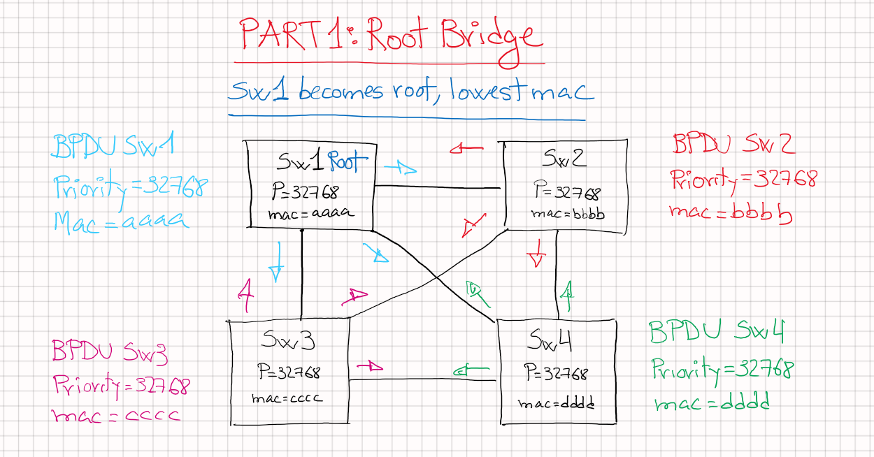
At the beginning, all the switches will send BPDUs that includes that switch configured priority and internal mac address.
Now, if a switch receives from one of its ports a superior BPDU (lowest priority or same priority but lower mac address) it will stop sending its own BPDUs.
The switch with the inferior BPDU lost the battle, and now it will be silent and will just send the winner BPDU through its other ports.
That way little by little only the superior BPDU of all switches will remain, the switch that is generating the lowest BPDU will be promoted to Root Switch.
Just two rules to elect the Root Switch:
- Lowest configured priority (default is 32768)
- If priority is the same, lowest system mac address wins.
Once a winner is elected, that switch will be the only one sending Configuration BPDUs(hellos) downstream. If you imagine the root at the top of the mountain
And the water is the BPDUs from the root, they only go downwards. BPDU behave the same, starts at the root and they just get moved downstream.
When a switch receives a Configuration BPDU from the root:
- Switch will look at it and update it with that switch information. Including that switch cost to reach the root switch.
- Will regenerate the BPDU and sent it downwards through its DP (Designated Ports), never back to the root.
Port roles and what they are used for
Root port: only one per switch (Root do not have any root ports). A root port is the lowest cost to reach the root. It’s the port from where we receive the superior BPDU.
Designated port: Only a port per segment (per link), a switch can have multiple DP. Switch closest to the root will have most of its ports as DP.
Blocking port: Inferior cost for the segment, on the other side of a blocking port will be a DP from a switch closest to the root bridge.
The role of these ports are calculated just after a Root Switch(aka bridge) was elected.
The 4 main events for STP convergence are:
- Elect a root bridge
- Find the Root port for each switch
- Find the DP for each switch
- Block the other ports
First: Elect a single Root Bridge
- Highest configured priority
- If same priority, lowest mac address wins
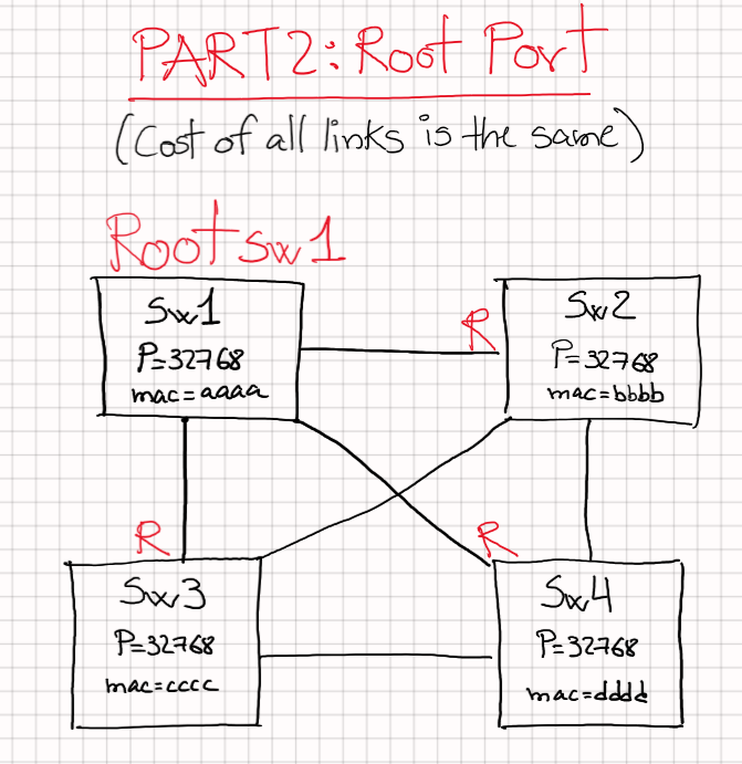
Second: After electing the root bridge, we have to elect a single root port, election rules hierarchy:
- Lowest RPC (root path cost). Basically, the shortest path to reach the root will be declared as a Root port.
- If the cost is the same, we check the sender BID(bridge ID) which includes:
- Lowest priority
- If priority is the same, lowest mac
- If the BID is the same, for example if we have several ports between two switches:
- Lowest port priority (by default is 128)
- If port priority is the same, lowest sender port id. From the other side perspective.
Remember: only a single root port per switch, only a single best path to the Root bridge. Root ports are forwarding traffic.
Notice that Root bridge do not have a root port, all its ports are designated.
Why? Well, there is not best path to yourself, the cost from root is 0.
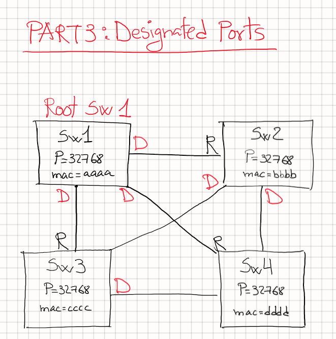
Third: After the root port, we have the DP election hierarchy:
- Lowest DPC, designated port cost, basically the switch that is closest to the root will win that. (lowest RPC)
- If the cost is the same, we check the sender BID(bridge ID) which includes:
- Lowest priority
- If priority is the same, lowest mac
- If the BID is the same, for example if we have several ports between two switches:
- Lowest port priority (by default is 128)
- If port priority is the same, lowest sender port id. From the other side perspective.
Remember: we can have and its normal to find several DP per switch. DP are forwarding traffic.
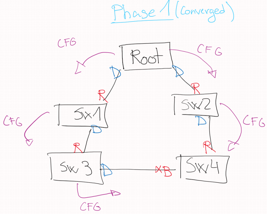
Note that Between Sw2 and Sw3, Sw2 wins due to lowest mac since their cost to root is the same.
Root will have always all its ports as designated ports.
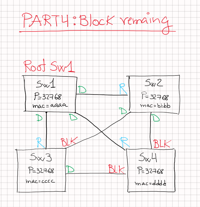
Fourth: Last part is to block any other ports; in the end the inferior ports will be set to blocking. A blocking port still listen to BPDUs.
Port status: the other side of the coin
We talked about how ports can be root, designated or blocking. But those port roles have a different status, some are forwarding and others are not.
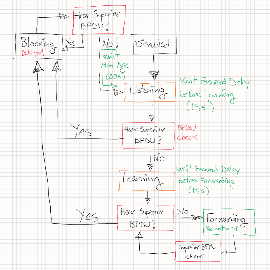
Just 5 status in PVSTP+:
- Disabled: admin down or unplugged. STABLE status.
- Listening: No data sent or received. BPDU are sent and received, no MAC learning. TRANSIT status.
- Learning: No data sent or received. BPDU sent and received. MAC learning. TRANSIT status.
- Forwarding: Data sent and received. BPDU sent and received. MAC learning. STABLE status.
- Blocking: No data sent or received. BPDU received, but not sent. No MAC learning. STABLE status.
Comments:
- MAC learning: we start installing any mac that we hear, and associated to an exit port so we can forward the traffic later.
- BPDU sent:
- After root election, the only switch(bridge) that creates BPDU is the Root, BPDU will go downstream through the DP.
- We are still re-generating the original Root BPDU (named Configuration BPDU).
- Our SW will update its cost to the root and pass the BPDU downstream through its Designated ports.
- TRANSIST or STABLE status: Transit means the port will move into another status and stable is that the port will remain like that.
Timers: They are never late
3 timers that have a role in this game:
- Hello timer: Interval between BPDU transmissions (2 seconds) from the Root bridge.
- Forward delay: Time spend in transient states (15 secs).
- Maximum age: Max time switch will keep the best BPDU (20 secs). This is just a hold-down timer.
Timer can be set locally in each switch, but the only timers that really matters are the timers set on the root.
Timers are included inside every BPDU, so all switches are up to date with the root configuration about timers.
Topology changes: What to do when your kitchen it’s on fire
There are 4 events that are considered by PVSTP+ as a change in the topology:
- When we receive a TCN (Topology change notification) from a downstream switch. Our switch will send another TCN upstream.
- When a port moves into forwarding and the switch has at least a DP. (not just a single root port and no other ports)
- A port goes from Learning or Forwarding into blocking.
- A switch becomes the root switch.
Process for topology changes:
- Before any events, Root will send CFG(Configuration)BPDUs, which are just hellos.
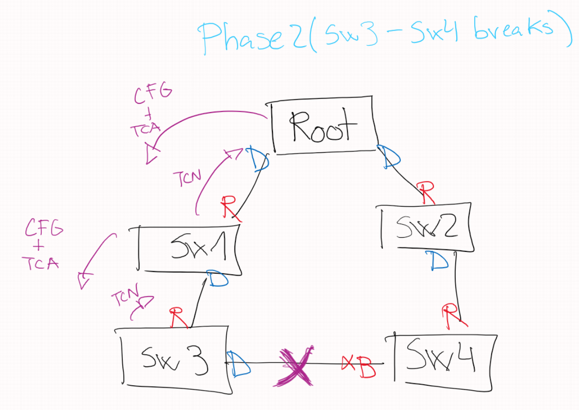
- TCN BPDU sent by the switch detecting a change using the root port only towards root. Link between SW3-SW4 fails.
- Hello time until forward delay expires or TCA is received from an upstream switch (it will send hellos every 2 secs until the forward delay timer or until receive a TCA from upstream).
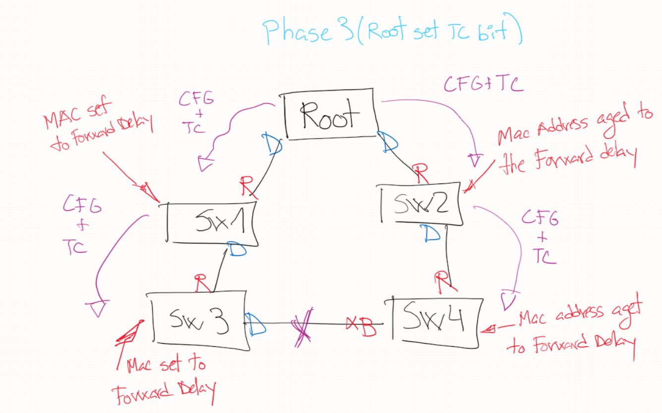
- Root receives the TCN and sets the TC bit in BPDUS, this signals the switches that somewhere a topology changed has happened.
- When the downstream switches receive the BPDU with the TC bit lower their MAC aging from 300 seconds default to forward delay timer(15s).
- TC bit set to 1 and sent with the BPDU configuration by the root switch is going to happen for Max age + forward delay = 20 + 15 = 35 secs by default.
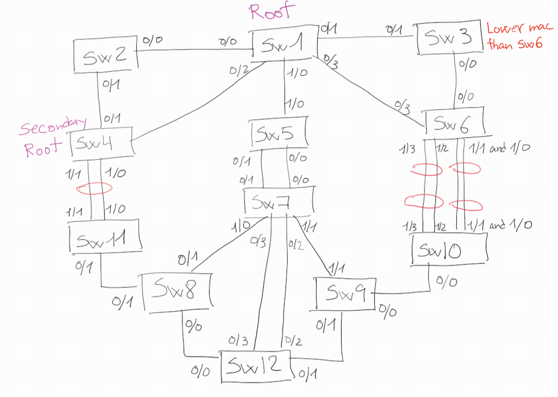
Final PVSTP+ port role challenge
To wrap up this post, I´ll put a challenge to set the ports of a more advance designed. I will post the answer in the next PVSTP+ post part 2.
Try to find out the role of each switch port: Root ports, DP and Blocking ports.
Note: Between SW4-SW11 we have a port-channel, and between SW6 and SW10 we have two different port-channels.
Conclusion
This was the first part of PVSTP+, not bad for an introduction.
STP still hides more interesting topics that will be covered in future posts such as Portfast or BPDUguard.
Until next time!


Recent Comments