Introduction
If you understood RPVST+ good enough, then for MSTP you have 50% of the homework done. It uses most of the concepts and improvements from RPVSTP+.
Furthermore, the content of the BPDU exchange in MSTP share many characteristics with RPVSTP+, like the port role that it is included in the Hellos.
Let’s dig deep into MSTP with some drawings!
Why would you want or not MSTP?
Two main benefits: Standard based(inter vendor operability) and Less control plane chattiness (BPDUs).
PVSTP+ and RPVSTP+ generates a BPDU per vlan, if you have 300 vlans, then you’ll see 300 BPDUs every 2 seconds.
MSTP evolves the concept allowing you to map several vlans into a single instance, called MST instance.(MSTI)
For example you can map vlans 10 to 20 into MST 1 and vlans 21 to 40 into MST 2 and still a single BPDU that contains information about both MSTI.
Inside a MSTP region we keep all the benefits of RPVST+ regarding the speed of convergence, but without a BPDUs sent per vlan.
The biggest drawback I’ll say is that is much more difficult to understand and predict its behavior in complex scenarios.
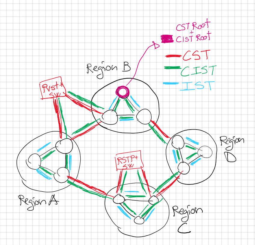
Main drawing:

Concepts before starting
We have to talk about some acronyms that are used in MSTP in every book or blog, that are quite confusing at first.
Region: A group of MSTP switches that share exactly the same configuration:
-
- Same revision number
- Same name of the region
- Same vlans to instance mapping
CST: Common Spanning Tree, this is the Level 1 the high-level overview.
This level considers every Region as a virtual Switch and any other PVST or RSTP switch.
- Each boundary represented with a new port role (Boundary port).
- When a switch detects BPDU messages sourced from another region (or STP/PVST+ BPDU), it marks the corresponding port as MSTP boundary.
- This is a single Spanning tree that connects all Regions together, check the drawing for the Level 1 of abstraction.
- One root for all regions, called the CST root!
- Bridge (Switch) with lowest bridge id(priority + mac) in mst0 of all regions becomes the CST root!
- Any external switch PVST or RPVST will be seen here also, at this level!! CST deals with interoperability!
- Red lines in the main drawing for the CST!

IST: Internal Spanning Tree.
Spanning tree running inside a Region, level 2 more deep zoom into our drawing.
Now we can see each region as a separate switch, that consider internal Region switch connections and also will elect a IST root.
- The IST root is elected for the whole region, named Regional Root.
- Only can be one Regional Root per Region.
- Regional root follows the same election rules as for root ports:
- Lowest cost to the CST root
- Lowest BID (priority + mac)
- Lowest Port id( priority + port number)
- Regional root is the root for the MST 0, it’s the only one that sends or receives BPDUs inside a region.
- If there are other MSTI(Instances)they will be attached together into this BPDU. There is only a BPDU per region originated by the Regional Root(IST root)
- Blue lines in the main drawing, inside each region we have our own IST.
CIST: Common Internal Spanning Tree.
It’s the spanning tree that goes everywhere and touch every switch and every region. Connects all together.
- See the green lines in the main drawing above!
- It’s also the default spanning tree instance of MSTP so that any VLAN which isn’t a member of a particular MSTI, will be a member of the CIST.

New Ports:
- Master port: all MSTP instances see the root port (towards the CIST Root) of the CIST Regional Bridge as a special Master Port connecting them to the CIST Root bridge.
- This port link all MSTI of all regions, MSTI information do not leave each Region. Only CIST information leaves a Region.
- Boundary port: It marks boundaries with another MSTP Region or with another Switch running PVSTP or RSTP.
Root election
CIST root election:
- At the beginning, all switches will declare themselves as CIST ROOT and CIST Regional Root inside a region. Outside a region(boundary ports) the border switch will advertise only the CIST root bridge ID and the cost to reach it.
- Who will win? The best Bridge id(priority + lowest mac; winning lowest priority) of all the Regions, for the whole CIST.
- Eventually every region will have one switch with a single pointing to the CIST Root(root port)
- CIST Root region will have all their boundary port as DP and forwarding( as a normal Root SW would have in PVST+ or RPVSTP+)
CIST Regional Root:
- It’s the MST0 root for that region, will be the Root for that region for all instances also. See later for some examples of traffic flow depending on where is set the Regional Root.
-
- 1st Lowest cost to reach CIST rootCIST Regional Root winner will be the one that wins in this election:
- 2nd Lowest BID priority inside the region(still higher than CIST root)
- Bridge priority
- Bridge mac
- 3rd Lowest sender PID
- Port priority
- Port id
- Only a boundary switch can be elected as Regional Root.
For example, if you examine Region D in the drawings, SW6 could not win.
-
- Changed priority on Region D, sw6 to be the best of the Region for MST0, and still the Regional Root is SW4. Sw6 is NOT a boundary switch therefore is not eligible to be Regional Root.

MSTP Operation
MSTI: Multiple Spanning Tree Instances
- By default all Regions have MST 0, that is share in all the CIST(green lines in the main drawing).
- Other vlans to instance mapping can be created, but whatever vlans not included in any instance will stay inside MST 0.
BPDUs:
- Inside a MSTP Region:
- MSTIS(MST Instances) do not send individual BPDUs. Every switch inside a region will send BPDUs, like a RPVSTP+ implementation.
- Each BPDU will include attached any other instance information at the end of the frame.
- Outside Regions:
- CIST Root will generate BPDUs, all the timers are taken from the config of the CIST root. BPDU will go downstream through the DP ports.
- This BPDU controls information between regions. That way also all regions can agree in a single best BID CIST root.
- Other Regional Root will replicate this BPDU, adding it cost to reach the CIST Root. Once the BPDU reaches a boundary router DP port, will be send to the next Region.
- Border Switches will received through their Root port the BPDU from upstream. Border Switches won’t sent back anything through their Root Port.
- When facing outside MSTP domain such as PVST+ or RPVST+
- CIST Root/CST Root(same switch)Will send one BPDU per vlan, like a normal PVST or RPVST+ will do. That way we have interoperability with other STP flavors.
PVST+ and RSTP+ interaction with MSTP:
- Connection between Region and other PVSTP+ or RPVSTP+ switches will be a boundary port and also, they will work as PVSTP+ behavior. Message sent are in PVST+ format.
- From SW7 towards the RPVSTP+ switches, port eth1/1 and eth1/2 are seen as Boundary PVST+, in the diagrams below where we add RPVST+ into the diagram.
- For retrocompatibility to work, CIST root MUST be within MSTP! A PVST+ or RPVST+ must not be the best priority switch!!
Packet Flow inside MSTP
I ran some tests to see and show the MSTP behavior, and see how the traffic follow the tree up to the CIST Root:
1.Ping from Region C PC-C6 towards Region D PC-D2, traffic went following the Boundary port towards the CIST.
PC-D2 mac address: aabb.cc01.1010


Ping inside Region D:
All PCs are inside vlan 10 access.
Region D Regional Root is SW4!
Instance 1: vlan 10-15 MST1 root SW4
Instance 2: vlan 16-30 MST 2 root SW5
2.Ping from PC-D3 towards PC-D2, since all PCs are inside vlan 10 the ping will follow towards MST 1 root first.
Path SW4-SW5, SW4 is the MST 1 root for vlan 10

3.Ping from PC-D1 Region D towards PC-D2 Region D:
All PCs are inside vlan 10 access.
Region D Regional Root is SW4!
Instance 1: vlan 10-15 MST1 root SW4
Instance 2: vlan 16-30 MST 2 root SW5

4.Ping from PC-D1 Region D towards PC-D2 Region D, but this time we move PC-D1 and PC-D2 to vlan 20 where SW5 is the root:
PCs moved to inside vlan 20 access.
Region D Regional Root is SW4!
Instance 1: vlan 10-15 MST1 root SW4
Instance 2: vlan 16-30 MST 2 root SW5
Traffic went SW6-SW5 direclty now, as SW5 is the MST 2 root and MST 2 instance have mapped vlan 20 for which the two PC belong in this last test.
We can conclude that traffic inside a Region will go first through the MST root for that vlan!


5. Ping between Regions, inside vlan 20 in this case.
PC-C-6 pings PC-A-5 inside vlan 20, path follows the MST 2 Root that includes vlan 15-30.

Wireshark captures
Listening to SW7 Region C port eth0/0 wireshark:

Other BPDU found in the the same port eth0/0 between SW7and SW8, this time check how also SW8 is sending BPDUs:

Adding retrocompatibility with PVST and RPVST


Connection between Region and other PVSTP+ or RPVSTP+ switches will be a boundary port and also, they will work as PVSTP+ behavior.
Message are sent in PVST+ format.
From SW7 towards the RPVSTP+ switches, port eth1/1 and eth1/2 are seen as Boundary PVST+:


From SW19/SW20 RPSTP+ root is always the Regional Root, which is SW7 for Region C.
Notice also how RPVST+ SW19 see MSTP as normal STP!

Wireshark:
SW7 port eth1/1:

From SW7, neighbor SW19 is reachable through Port eth1/1 that it is considered just a PVST neighbor.
We have a few received BPDU that were generated during convergence, as with classic PVSTP only the root will send BPDU the Sw19 went silent as its BID is inferior. Classic PVST behavior.

From SW19 RSTP switch, we have one BPDU per vlan, see how we receive one BPDU from SW7 for each vlan, like a classic PVST+. SW 19 stopped sending BPDUs, number do not increase.

References/ Further reading:
https://blog.ine.com/2010/02/22/understanding-mstp#IMPLEMENTING_MSTP
https://support.huawei.com/enterprise/en/doc/EDOC1100066160/f7e8e63c/basic-concepts-of-mstp
https://en.wikipedia.org/wiki/Multiple_Spanning_Tree_Protocol
https://www.cisco.com/c/en/us/support/docs/lan-switching/spanning-tree-protocol/24248-147.html
*My own research and testing in lab
Conclusion:
I spent more than 20h researching, taking notes and testing to write this post. Most difficult post so far, I hope that you like it!
This is most of the MSTP that you should know, we didn’t talk about best designs and load balancing. But maybe for another post!
Check the references above if you want to learn more.


Recent Comments